Technical Readiness Guide
From artwork color modes to liquid viscosity matching. A comprehensive engineering handbook for Quality Control (QC) managers and packaging designers.
1. Pre-Fill Design: The Color Mode Protocol
Before a single bottle is filled, the decoration must be perfected. A common cause of production delays is the mismatch between Digital Design (RGB) and Physical Production (CMYK). This affects not just aesthetics, but also the compatibility with optical sensors on automated filling lines which rely on contrast detection.
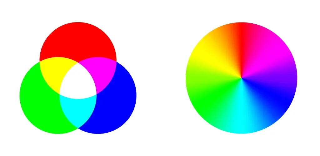
RGB vs. CMYK: The Critical Difference
Screens emit light (Red, Green, Blue), while printers reflect light (Cyan, Magenta, Yellow, Black). Designing in RGB for physical packaging often leads to “dull” results when printed.
Our Requirement: All artwork files submitted for Silk Screen, Offset, or Heat Transfer printing must be converted to CMYK mode. Spot colors should be defined using Pantone (PMS) Solid Coated codes.
Digital Pre-Visualization
We provide 3D digital renderings to simulate the liquid fill line against your artwork. This ensures that the product level doesn’t obscure critical branding elements or regulatory text.

2. Fluid Dynamics: Headspace & Overflow
Headspace (Ullage) is the volume of air left in the container after filling. It is a critical safety buffer for thermal expansion.
The 5% Rule
Liquids expand when heated (e.g., during shipping in a hot container). If a bottle is filled 100% full, the hydraulic pressure from expansion can deform the bottle (“bloating”) or pop the cap off. We recommend a minimum 5% to 10% headspace.
| Bottle Size | Rec. Fill Volume | Actual OFC (Overflow) | Headspace % |
|---|---|---|---|
| 100ml | 100ml | 108ml – 112ml | ~10% |
| 250ml | 250ml | 265ml – 270ml | ~6-8% |
| 500ml | 500ml | 525ml – 535ml | ~5-7% |
Exception: Airless Systems. Pour Airless Bottles, the rule is reversed. You must fill close to the top to ensure the product touches the pump mechanism, priming the vacuum system immediately.
3. Rheology & Pump Matching
Viscosity (measured in Centipoise/cps) determines the flow resistance of your liquid. This dictates which filling machine nozzle and which dispensing pump engine we must use.
Viscosity Reference Chart
Equipment Implications
- Low Viscosity (< 2000 cps): Use Gravity or Overflow Fillers. Pump Choice: Fine Mist Sprayer.
- Medium Viscosity (2000 – 15000 cps): Use Piston Fillers. Pump Choice: Standard Lotion Pump (1.5cc dosage).
- High Viscosity (> 20000 cps): Requires Piston Fillers with “Suck-Back” nozzles to prevent stringing. Pump Choice: High-Viscosity Cream Pump or Airless System.
4. Capping Torque Standards
“Torque” is the rotational force applied to the cap. Incorrect torque is the leading cause of leakage during transit.
| Taille du cou | Application Torque (in-lbs) | Removal Torque (in-lbs) |
|---|---|---|
| 18mm / 20mm | 6 – 9 | 3 – 6 |
| 24mm (Standard) | 10 – 14 | 6 – 10 |
| 28mm (Pump) | 12 – 16 | 8 – 12 |
Relaxation: Plastic is viscoelastic. After capping, the torque will naturally “relax” or drop by 30-50% over 24 hours. The “Removal Torque” specs above account for this relaxation to ensure the consumer can still open the bottle.
Filling Troubleshooting FAQ
Need Engineering Support?
Send us your product specs (viscosity, pH, temperature) and we will recommend the perfect packaging configuration.
Consult an Engineer